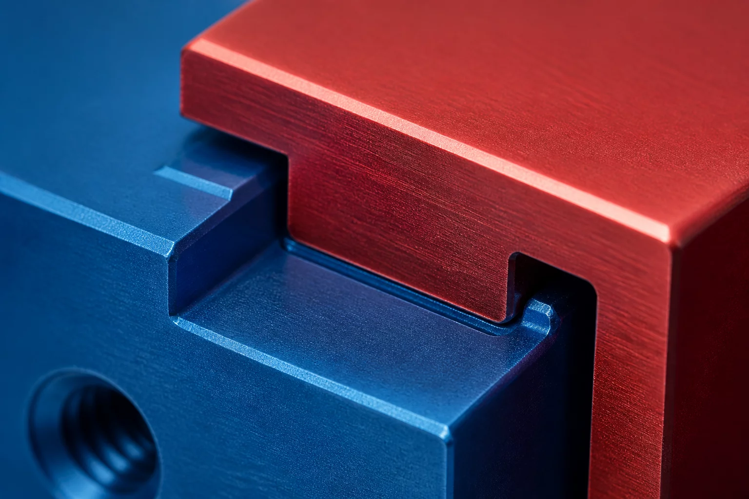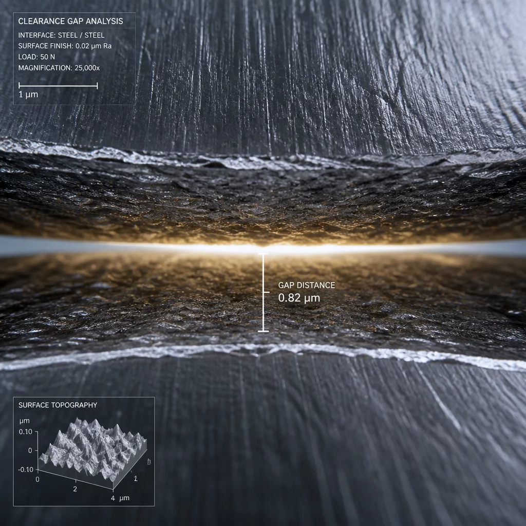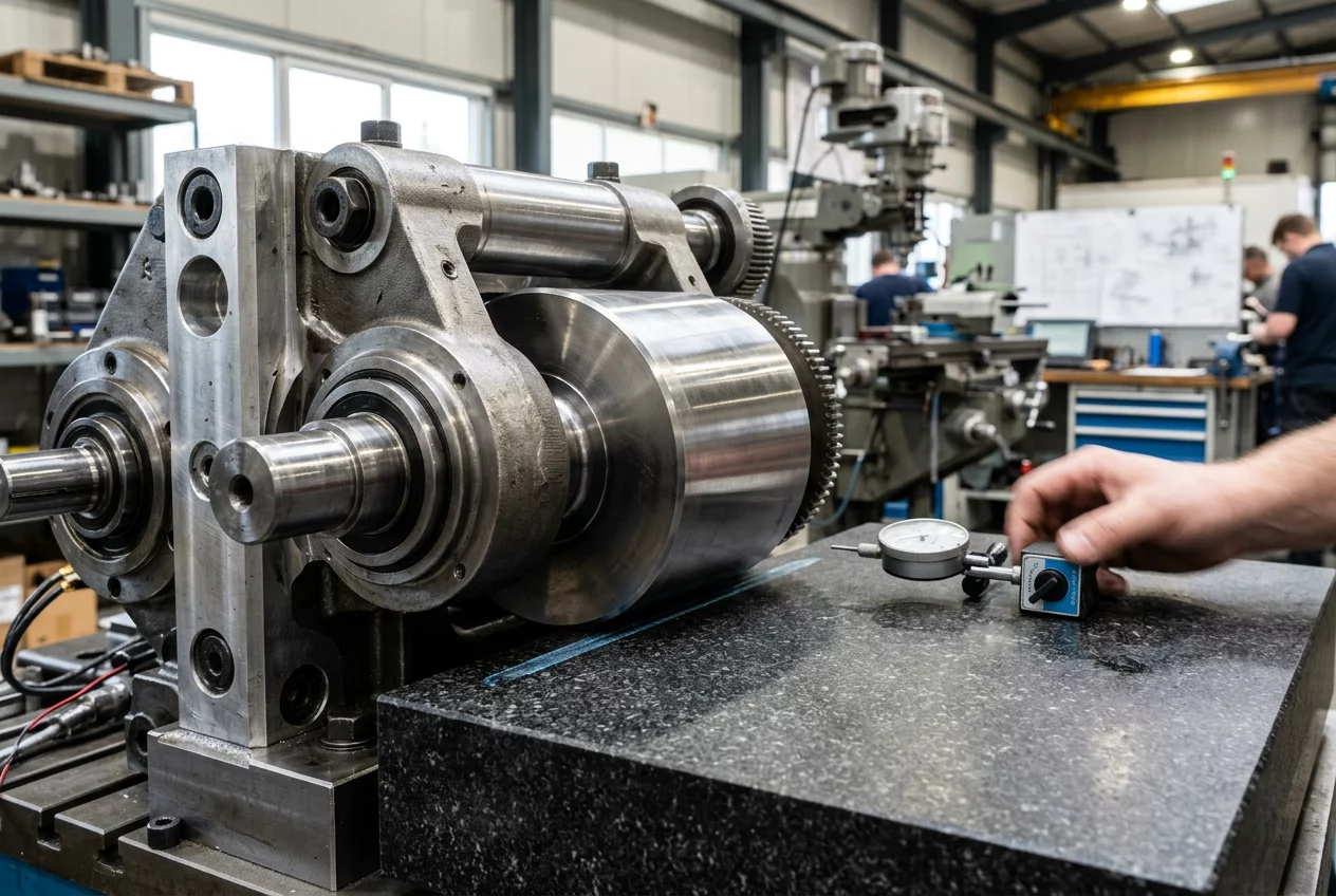
Tangency constraints play a critical role in assembly design, aligning curved surfaces with flat planes or other cylinders. In CAD software, a tangency constraint reduces degrees of freedom by forcing two surfaces to share a common tangent plane at their interface. However, translating this mathematical perfection to real-world components introduces significant tolerance challenges. Because physical parts always deviate from their nominal dimensions, the actual contact point on a curved surface will shift. This variation directly affects the assembly's overall alignment, clearance, and functionality.
Core Concepts & Methodologies
When performing tolerance stack-up analysis, standard linear equations often fail to capture the behavior of tangency constraints. A small dimensional change in a cylinder's diameter or a plane's location can cause a disproportionately large displacement of the contact point. Engineers must map these non-linear dependencies to predict where parts will actually touch. Understanding how geometric tolerances like cylinder circularity and surface profile affect these points ensures that assemblies fit together properly without interference or excessive play.
- Master non-linear tolerance stack-up calculations for curved surface interfaces.
- Prevent assembly failures caused by unexpected shifting of tangent contact points.
- Apply appropriate GD&T controls including profile and runout tolerances.
- Optimize assembly constraint strategies within Fusion 360 and similar CAD systems.