FitChange Handbook

Review What a Part Change Does to Everything Around It

Use practical engineering questions to examine interfaces, clearances, dependencies, assumptions, and revision impact.

Core Assessment Focus

Mating Interfaces

Do mating surfaces align and match constraints after modification?

Clearance Gaps

Will stack-up tolerances cause physical interference or collision?

administrator

Revision Impact

How does a single dimensional shift propagate to adjacent parts?

Interactive Framework

Geometric Integrity & Tolerance Verification

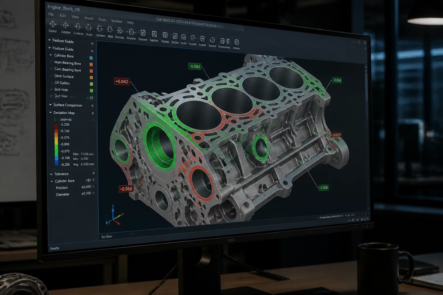
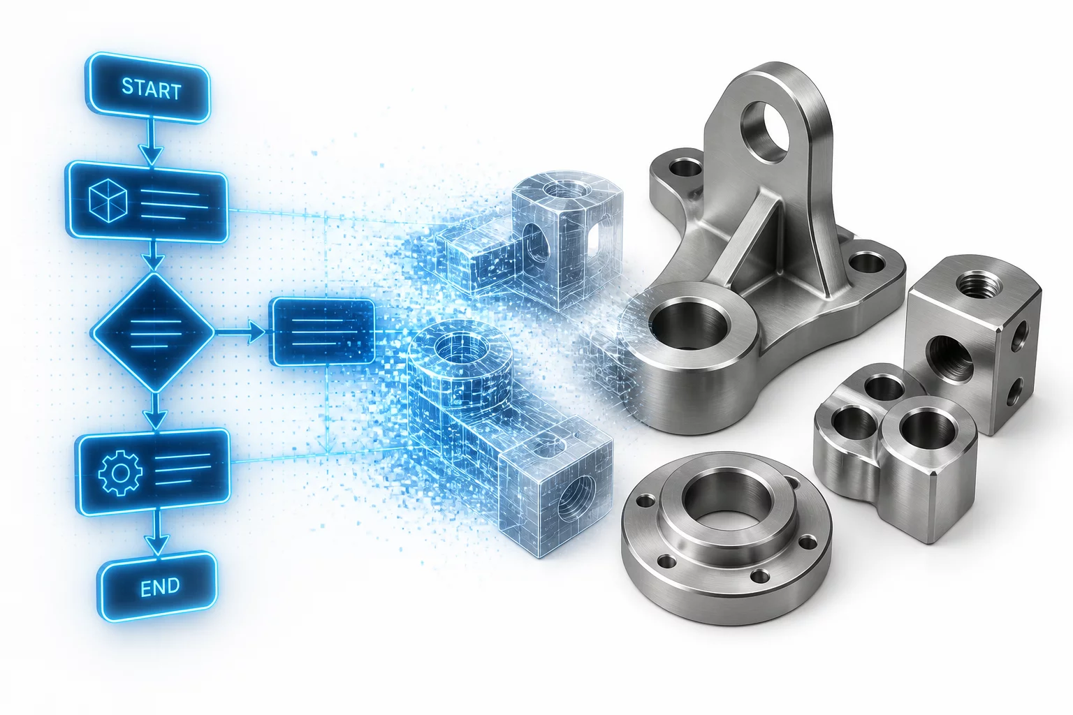
Prevent assembly failures by mapping geometric links. Our structural guide provides the exact question flow diagrams needed for mechanical design validation, ensuring every revision is checked against neighboring clearances.

3D
CAD Dependency Mapping
Zero
Interference Tolerances
Full
Revision Alignment
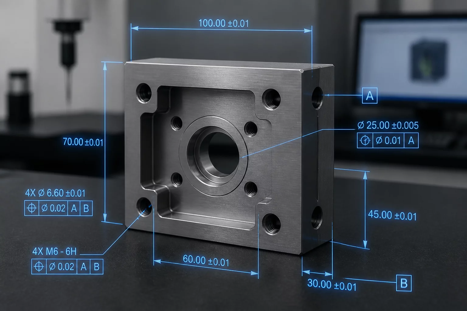
Assembly Interface Review
Handbook Topics

Core Dimensional Engineering Topics

Explore how geometric alterations propagate through assemblies and affect adjacent components.

Assembly Clearance
Tolerance

Assembly Clearance

Analyze minimum and maximum clearance bounds to prevent component interference during operation.

Mating Interfaces
Tolerance

Mating Interfaces

Define and control critical contact surfaces where physical parts meet and align.

Tolerance Assumptions
Tolerance

Tolerance Assumptions

Evaluate statistical and worst-case scenarios for dimensional variations in production.

Neighboring Components
Workflow

Neighboring Components

Identify adjacent parts affected by localized dimensional modifications.

Downstream Consequences
Workflow

Downstream Consequences

Trace secondary effects on tooling, assembly fixtures, and final inspection.

Revision Approval
Workflow

Revision Approval

Establish standardized workflows for signing off on geometric changes.

Tolerance Analysis

Core Engineering Materials

Explore the critical geometric changes, part interfaces, and tolerance stack-up analysis that govern precision assemblies.

Assembly Interface Review
Interface Jul 15, 2026

Assembly Interface Review

Analyze how component mating faces interact and how small geometry modifications propagate through the assembly.

Clearance Change Checklist
Clearance Jul 10, 2026

Clearance Change Checklist

A step-by-step verification checklist to ensure gap clearances remain within safe operational limits after design updates.

When One Dimension Affects Three Parts
Tolerance Jul 05, 2026

When One Dimension Affects Three Parts

Understand the complex cascading effects when a single dimensional change impacts multiple neighboring parts simultaneously.

Tolerance Assumptions
Tolerance Jun 28, 2026

Tolerance Assumptions

Identify and validate implicit assumptions in stack-up analysis to prevent assembly failures during production.

Downstream Revision Impact
Revisions Jun 20, 2026

Downstream Revision Impact

Assess how revisions in early design stages influence manufacturing, tooling, and final inspection processes downstream.

Fit Decision Case Studies
Case Studies Jun 15, 2026

Fit Decision Case Studies

Real-world engineering scenarios showing how tolerance allocation decisions resolved critical interference issues.

Engineering Handoff Questions
Handoffs Jun 10, 2026

Engineering Handoff Questions

Essential questions to address during design handoffs to ensure manufacturing teams fully understand critical tolerances.

Interactive Demo

Simulate Downstream Tolerance Stack-Up

Modify the dimensions of individual parts below to see how minor changes cascade through the assembly. Real-time calculations demonstrate why neighboring clearance is critical.

Assembly Dimensions

Part A (Base Plate) 50.0 mm
Part B (Mating Bracket) 30.0 mm
Part C (Retaining Clip) 15.0 mm

Live Assembly Blueprint

Housing Space: 100.0 mm
Part A
Part B
Part C
Gap

Analysis Report

5.0 mm

Assembly is stable. The clearance gap is within safe design tolerances.

Engineering Certainty

Overcoming Design Hesitations

Modifying component geometry always carries risk. FitChange Handbook provides the exact rules to predict how a change in one part affects the entire assembly interface.

Still Unsure?

Select any of the common engineering concerns on the right to see how we address them.

Explore Programs

Is the training worth the resource allocation?

A single tolerance stack-up error in production costs multiple times the price of this handbook in physical scrap and tooling rework. By mastering interface control, you eliminate downstream manufacturing errors before they reach the shop floor.

How much time does this require?

The handbook is structured as a modular reference guide. Each technical brief takes under 15 minutes to read and apply. You do not need to pause your daily workflow; simply consult the relevant chapter when modifying your active CAD models.

Is the geometric math too complex?

We avoid abstract academic formulas. The material focuses entirely on practical assembly relationships, standard clearance calculations, and mating constraints. If you can read a standard blueprint and use basic CAD constraints, you will easily follow the methods.

What if I encounter unique assembly challenges?

Every participant gains access to our digital engineering community. You can share anonymized component diagrams, ask questions regarding complex stack-ups, and receive guidance from experienced CAD coordinators.

Workflow & Handoff

Precision Geometry Review & Approval Stages

Explore our structured engineering checkpoints. Understand exactly what data is reviewed and what criteria are approved at each phase of the design loop.

Stage 01

Mating Interface Mapping

Identify mating surfaces and component constraints to establish the geometric baseline.

Stage 02

Tolerance & Clearance Simulation

Analyze dimensional deviations and clearance margins using statistical stack-up models.

Stage 03

Downstream Impact Analysis

Map component dependencies to predict how a change propagates to adjacent parts.

Stage 04

Handoff & Fit Certification

Finalize production-ready documentation and quality inspection protocols.

Stage 01 Initial Handoff

Mating Interface Mapping

Before any physical prototype or final drawing is produced, we map every contact zone. This step defines how component surfaces interact under load and limits cumulative error.

What You See

  • CAD alignment models
  • Primary mating surface maps
  • Clearance constraint matrices

What You Approve

  • Baseline assembly interfaces
  • Reference coordinate systems
  • Initial datum selections
Stage 02 Analysis Checkpoint

Tolerance & Clearance Simulation

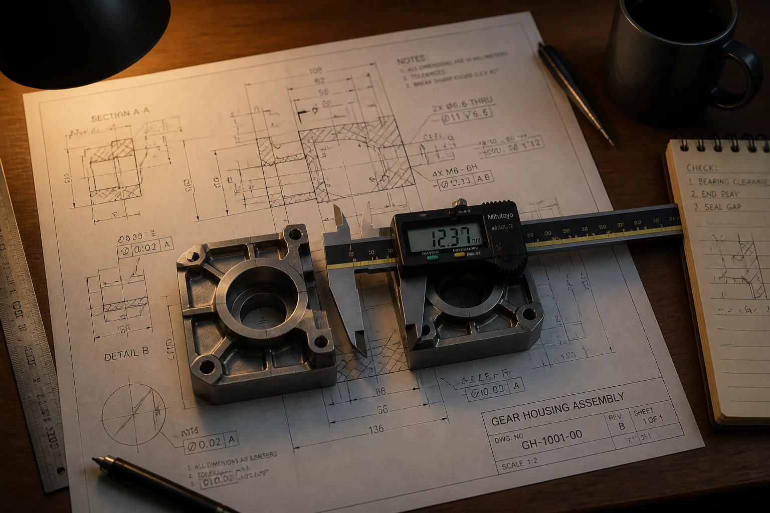
We apply statistical stack-up analysis to simulate manufacturing variations. By checking worst-case scenarios, we guarantee that parts fit together even at the limits of their tolerance bounds.

What You See

  • Worst-case interference models
  • Statistical stack-up reports
  • Digital caliper measurements

What You Approve

  • Clearance safety margins
  • Acceptable tolerance limits
  • Tangency constraint offsets
Stage 03 Impact Evaluation

Downstream Impact Analysis

A single dimensional shift can trigger failures in adjacent components. We map the dependency chain to ensure that changes in one part do not compromise assembly integrity or tooling setups.

What You See

  • Component dependency maps
  • Downstream tooling warnings
  • Revision history logs

What You Approve

  • Sensitivity thresholds
  • Multi-part revision paths
  • Mating interface updates
Stage 04 Production Ready

Handoff & Fit Certification

The final phase locks the geometry. We package the verified CAD models, 2D drawings with GD&T callouts, and inspection criteria to certify the assembly for manufacturing.

What You See

  • Fit-review handbook certificate
  • Technical handoff checklists
  • Standardized inspection plans

What You Approve

  • Release-to-manufacture package
  • Quality inspection criteria
  • Final sign-off documents
Educational Programs

Geometry Change Fundamentals

Explore how alterations in component dimensions and tolerance stack-ups directly impact mating interfaces and neighboring parts.