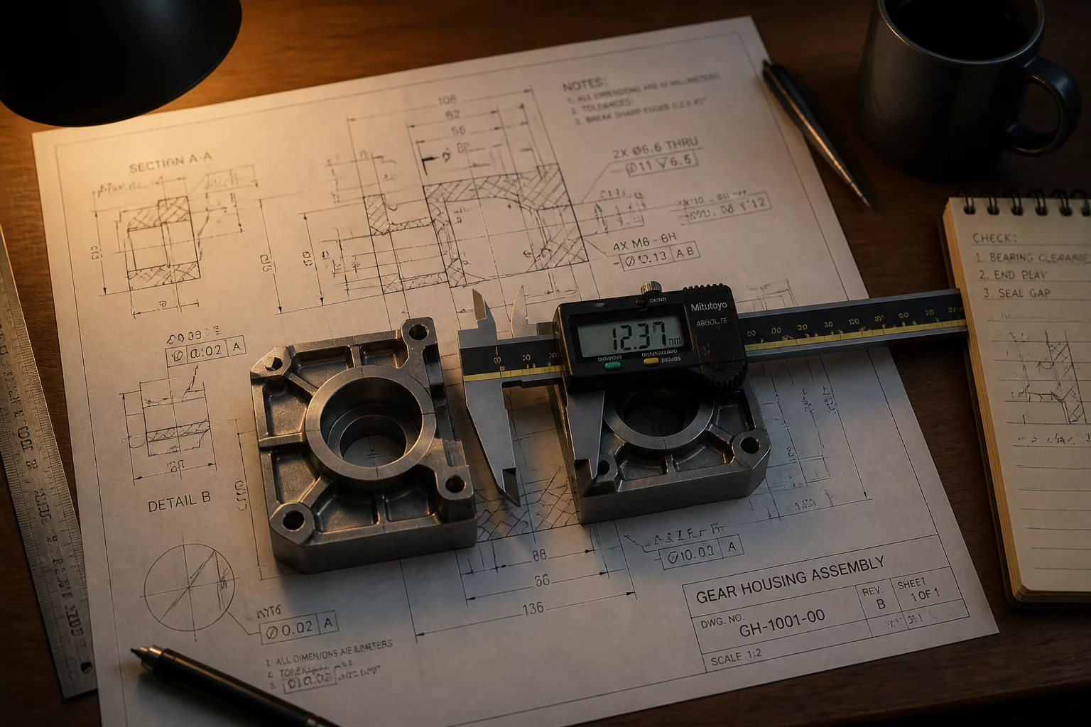
When engineers modify a physical component's dimensions, the change cascades through the entire assembly. Even a microscopic adjustment to a mating plane or diameter alters the physical clearance boundaries, which often leads to critical interference issues or loose fits. The Clearance Change Checklist functions as a systematic verification tool, helping mechanical design teams track how geometric variations affect adjacent parts. It ensures that nominal gaps remain within acceptable functional limits under all conditions.
Core Concepts & Methodologies
Applying this checklist requires an understanding of how component stack-ups build up in an assembly. Instead of analyzing a single component in isolation, engineers must map the interface tolerances from the reference datum to the critical clearance gap. This structured checklist guides you to check minimum assembly clearances, account for maximum material conditions, and verify potential thermal expansion effects. By running these checks, engineering teams systematically reduce the risk of physical collisions on the manufacturing floor.
- Map component dependencies to identify all adjacent parts affected by a single geometric change.
- Calculate the worst-case and RSS tolerance stack-ups for every altered assembly interface.
- Verify that minimum clearance requirements satisfy structural, dynamic, and thermal operational limits.
- Document and sign off on clearance changes to maintain clear version history across CAD revisions.