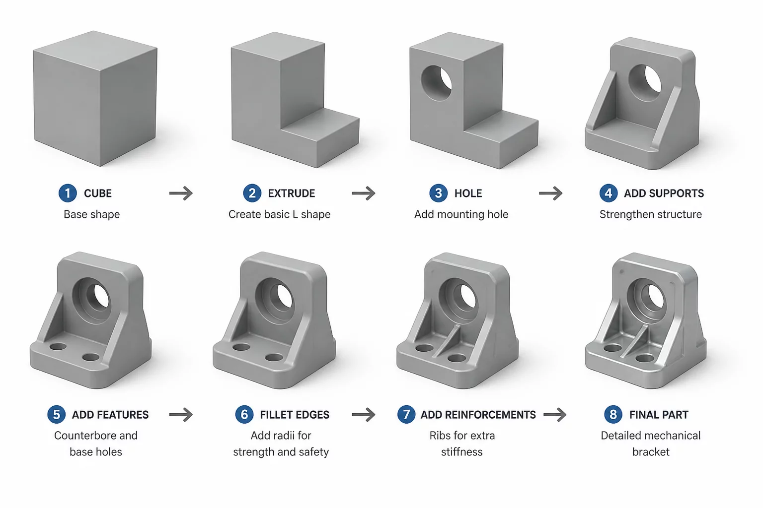
When designing mechanical assemblies, modifying a single component rarely happens in isolation. Any alteration to a face, flange, or fastener hole can immediately shift the operating environment of neighboring parts. This course details the engineering methodologies used to trace, calculate, and mitigate these cascading effects. You will learn to recognize how subtle dimensional updates shift the local coordinate systems of mating parts, resulting in unintended interface interference or excessive clearances.
Core Concepts & Methodologies
To prevent manufacturing defects, engineers must perform a multi-directional boundary review before approving any design change. Our curriculum focuses on mapping component dependency paths. This ensures that when Part A is updated, the downstream adjustments on Part B and Part C are mathematically quantified and controlled. We explore real-world cases of structural shift, thermal expansion clearance changes, and dynamic alignment changes in precision assemblies.
- Identify critical clearance boundaries and design constraints between mating components.
- Establish deterministic coordinate systems to predict cascading tolerance shifts accurately.
- Calculate cumulative deviation across multi-part interfaces using statistical stack methods.
- Minimize expensive tooling re-works by validating adjacent boundaries in CAD early.