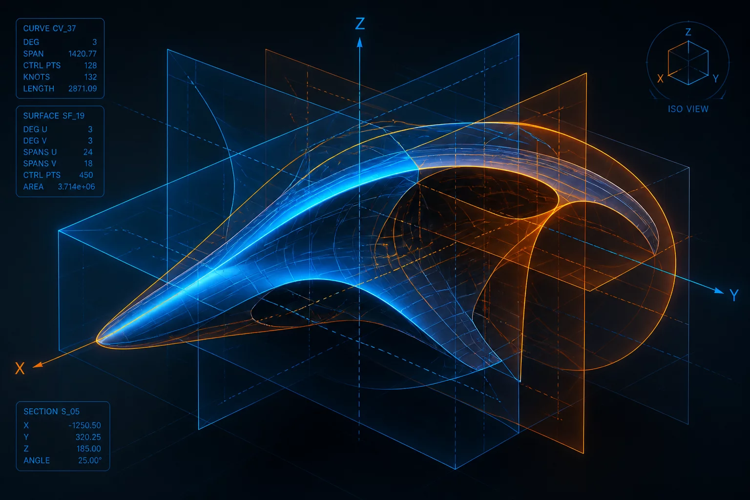
Construction geometry represents the primary frame of reference in computer-aided design (CAD). Reference planes, coordinate axes, and theoretical points do not physically exist in manufactured parts, yet they establish the foundation for all assembly interfaces. When adjusting construction geometry, engineers must understand that even minor shifts can propagate downstream, altering tolerance stack-ups and mating clearances across multiple components.
Core Concepts & Methodologies
Establishing stable reference features is essential for maintaining control over component alignments. Using dynamic reference frames that depend on unstable transient geometry often leads to model breakage and manufacturing defects. By adopting best practices in construction geometry construction, teams ensure that engineering modifications remain predictable and that assembly interfaces satisfy their design specifications.
- Identify how variations in construction planes propagate through component stacks.
- Build robust reference frames that isolate downstream engineering changes.
- Manage complex multi-part alignments with predictable constraint logic.
- Minimize assembly failures by avoiding daisy-chained geometry references.